Introduction to ByPic
This is an interactive language that fits onto a microcontroller chip, this means that to program the chip all you need is a serial interface. ByPic is on several hardwares from a single chip to PCB's but the same applies and so this tutorial will take the simplest from (a single chip) as a step by step guide.
Step 1
Establish a serial connection with the chip (PCB board)
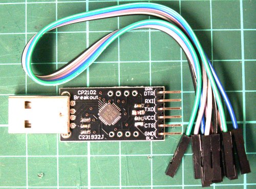
This is a typical USB to serial interface. It can also supply the power to the IC / PCB. If using a PCB then simply connect it up. All PCB have a 5V regulator and so use the 5V output. If using a chip use the 3.3V output. (More information on these devices.)

Use 5V supply for PCB, this is a BV507
If using an IC then some wiring will be needed:
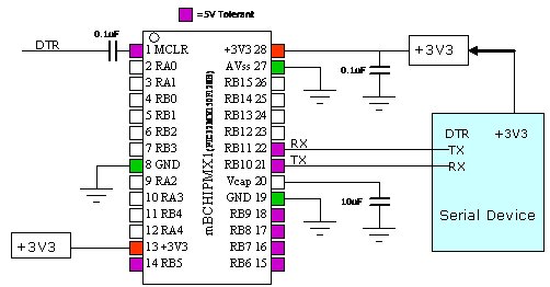

IMPORTANT the IC supply voltage is 3.3V - make sure that you choose the 3.3V output on the USB to serial device.
Summary of connections for enabling communication
| USB to Serial Pin | PCB Pin Name | DIL 28 pin IC MX1 Pin Number |
| RX | TX | 21 |
| TX | RX | 22 |
| +5V | +V | Do Not Use 5V on IC** |
| 3.3V | N/A | 13,28 |
| DTR * | DTR to Reset | (see breadboard circuit) |
| GND | GND | 8,19,27 |
Step 2
The device by default is 115200 Baud and will connect to any terminal, however use BVSerial as this will make programming easier.
Download BVSerial version 17, unpack to a folder and double click on the .exe file (Windows only, sorry).

If everything is connected okay and you have chosen the correct com port you will see the 'ok' prompt. If not check the troubleshooting at the bottom of this page.
Step 3: Type in the terminal area:
- print 12 + 12
- print 44.721 * 33.96
- print "hello world"
The * is a times and the hello world MUST have double quotes at the start and end.

This is the interactive nature of ByPic.
Variables
- Integer variables a,b fred, myvariable16 another one
- Floating variables a#,b#, myfloat12#
- String variables a$,b$, my_sting$
Step 4: Enter dim a,f#,s$ in the terminal area then press enter
That has created three variables of three different types, integer, floating point and string.
Step 5: Enter:
- a = 33
- f# = 22.4
- s$ = "Hello World"
You have placed some values in those variables

Variable can be used as normal try:
- print a + 7
- print s$ + " World"

Programming
We can of course do all the programming in the above terminal but mistakes are awkward to correct and we would not be able to save our work, so an editor is needed:
Step 6
Type .edit in the terminal window (that is dot edit). This will bring up the text editor.
Copy an paste the following:
function myfunc()
dim j
for j = 1 to 5
print "hello Me"
next
endf

Now press F4 (function key 4) and the program (function) will be immediately transferred to the CHIP or PCB.
In the terminal window type myfunc()

Typeing the name of a function will run that function. It doesn't look very nice so add \r\n to the end of the hell me line thus:
- print "hello Me\r\n"
Press F4 to reload and type myfunc() again. (HINT, the up arrow key will reproduce the last line typed 'myfunc()' and so there is no need to type it in again)

Notes
You can send the modified text or other text as as times as you like, it is stored in the devices RAM ready for running. A function can call other functions and a program is built of many functions. Each one can be tested individually. There are also library functions that have already been written to drive the I/O pins for example or perhaps an LCD display. These can be included or added to your own functions.
One possible way of thinking about this is that the functions are like the component parts of a machine, one all of the parts have been created the machine can be put together and also just like in engineering some of the parts can be put together as an assembly and tested before going onto the machine. This is exactly the same for functions.
>>>>> Next - creating a simple traffic light
Troubleshooting
Provided you have checked the wiring and made sure that 3.3V has not been exceeded* the only complication is the serial connection. Here are some pointers:
* Applies to IC only as PCB's work on 5V
- Check that you are using the correct COM ports. There may be several on the system, refresh the ports by typing .port and selecting the correct one, unplug the USB to serial, refresh the ports again and see which one is missing.
- Check that the TX (pin 21) goes to the RX of the serial device, if not sure swap them round. No harm will be done if they are the wrong way round. Type 3 in fact is TX to TX and RX to RX so swap them round anyway just to try it. Reset should bring up the sign-on screen.
- Establish that the USB to serial is working with BVS by connecting TX to RX and typing something in to BVS, what you type in should be echoed back.
- It is possible that one of the leads belonging to the USB to Serial is open circuit, check them.
- Uninstall and re-install the CP210x drivers, particularly if 3 above doesn't work.
- (Applies to breadboard only)Is the Vcap in place, on the right pin and the right way round (+ end goes to pin 20)
- (Applies to breadboard only)Is there 2 power connections and 3 ground connections - check.
- Check the Baud rate, stop bits and data bits are correct, 115200, 1 or 2, 8.
- If the USB to serial and BVS are working as 3 above; use the alternate reset circuit and replace DTR with a push button to ground – or a bit of wire that can be momentarily connected to ground. Connecting to ground causes a reset at which point data will come out of pin 21. You will be able to see this if you have the RX pin on the USB to serial connected to the TX pin on the IC.
- (Applies to breadboard only) If no data is coming out then the wiring is incorrect, is the chip the correct way round? Pin 1 is next to the dot and notch on the IC. Are all three ground connections in place? Are both power connections in place? Check Vcap again, is it the correct way round.
- If you can receive data but not send it then try re-installing the driver for the USB to serial device. Type 1 is particularly prone to this if you have had a previous driver for some other device installed.
- If data is coming out but nothing appears on the terminal then check the Baud rate is set to 115200 also make sure any hardware handshaking is turned OFF this will prevent any information from getting through, reinstall the com port drives again.
- (Applies to breadboard only) If the voltage has been exceeded or the supply has been connected the wrong way round then the IC will be destroyed. Note that all IC's are programmed and checked before shipping and so a faulty IC will not have been supplied. If you suspect this has happened then return the IC for checking.
- (Applies to breadboard only) It is all about confidence, keep trying and you will get it going eventually, check and double check. It is a simple circuit but any single error will cause it not to work. Most of all assume that the IC is okay and it is your wiring or set up that is wrong. If you assume that the IC is faulty then just give up now as you will never get it working.