IoT WiFi
Since the IoT Wifi introductory kit was introduced last year the ESP WiFi module firmware has been updated by ByVac and no longer resembles the original firmware. The transformation is considerable and so the need for this text. The original text can be found here.
Introduction
What follows is some practical examples using a BV508 a LED and switch. It has bee purposefully kept as simple as possible so that the user has something to build on.
Firmware Update
Before proceeding both the BV508 and ESP require firmware updates:
- Update the ESP to the latest version at least F1.9.13 < details of how to do that
- Update the ByPic firmware to the latest (98) (although not as necessary)
- Update to BvSerial 17 (important for #includes)
Circuit
For the exercises below, connect an LED to C0 and a switch, push button or simply a wire to C1.
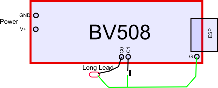
Connect the long lead (+ve) of the LED to C0 and the short lead to ground. For the switch a simple piece of wire will do that can be connected from C1 to ground. Supply power to the device but it is not necessary to connect the serial cable.
Preparation
The ESP on the BV508 will not work by default as it has the power down line connected to RA1 which needs to be brought high in order for the ESP to work. In hindsight this should really have had a pull up resistor, anyway run this script in the IDE:
http://www.byvac.com/downloads/BV508/u2.bas
Remove the serial cable (TX/RX) and just power up the BV508. Leaving the TX and RX in place will compete with the TX and RX on the ESP.
UART2
The ESP can be usefully connected to either UART1 or UART2, after prepping above connect the ESP to UART2. On the BV508 there are some solder jumpers that require shorting. Look for the 'JRX, JTX Jumpers' heading. Older versions of the BV508 had the ESP permanently connected to UART1, if this is the case then skip this section and go to the UART1 section.
Step 1
This assumes the following. You have set the ESP device to be a station and have got an IP address as per the quick start instructions. You are using BVSerial as the IDE.
It is better NOT to connect the TX and RX form the USB to Serial as it will interfere with communication. The power from the USB to Serial can be used though.
In this instance, open BVSerial and instead of connecting to COMn use a socket. In my case the IP socket address is 192.168.11.30:80 (put your own IP address in)

Things to check if it does not work:
- Only one BVserial can be opened at once - have you left the other one open
- Make sure that the PD pin on the ESP is high, if not see preparation again
- Ping the ip address make sure that it responds
We are now connected to the BV508 via wifi and can do all of the normal things that you would do over a serial link so u2.led(1) will turn on the LED
Why is this useful? Imagine prototyping a clock on the wall, no need to get it down to change the program. In other words the program can be changed in situe. Also remote items can be controlled by typing in the function name as above (u2.led(1)).
HTTP
We can go further than this though. Close BVSerial and open a browser and put in the text in the address bar as shown (use your own IP address)

The %0d is carriage return (in HTML speak) and the above is simply equivalent to pressing CR or ENTER at the keyboard when using BVSerial. See the ok prompt is returned (don't mind if there is ERROR as well).
Side Note: The ESP will send the data back from the BV508 when it receives a special character (26) and if using the latest version of ByPic there is a 26 on the end of the ok prompt. This is invisible to most terminals so you would not notice that it is there.
Try also sending 'http://192.168.11.30/u2.led(1)%0D' This will turn the led on, so you now have control from a browser.
Javascript
click on this link http://www.byvac.com/downloads/BV508/u2.html put in your own ip address and your good to go.

This is just a web page with some javascript it is on the ByVac server for convenience but can just as easily be run locally. Here is the source code for the web page.
Normally to do this kind of thing a server would be required, here we can do everything locally in javascript. What does this mean? Well we can write an application using javascript and put this on the net, no installation is required so it can run anywhere a browser can run. Just as above - click the URL and run some hardware - phone, PC, tablet, TV.
Side Note: Normally a browser will not entertain code form another source for security reasons. We are obtaining the browser page from byvac.com yet addressing the local wifi. The reason this works is because the ESP has specified a cross site origin in its header.
Using UART2 we are directly talking to the interpreter and so can basically do anything you can do over a COM port. Functions can be the basis of the application, if you want to do something then simply call a function.
UART1
We can do everything on UART2 as we can do on UART1 so why bother. There are some advantages when using UART1 as it gives greater control. The following will show how to create a RESTful like interface.
This will look like the following put in the address bar of a browser:
192.163.11.30/led/on
192.163.11.30/led/off
The idea (I think) is just to separate the functionality with '/'. So if you happen to have 2 sets of 8 relays say one controlling downstairs and the other controlling upstairs then this would make sense:
192.163.11.30/downstairs/relay_1/on
192.163.11.30/upstairs/relay_6/off
It seems to make a lot of sense and the commands are very easy to remember. The alternative is to use a query string: 192.168.11.30/?downstairs&relay_1=1 (not so easy to remember).
Preparation
This will require some software as we need to manipulate what is coming in and going out through program control.
Move the solder jumper back so that the ESP is now on UART1, connect up the USB to Serial and use the BVSerial IDE in the normal way.
Side Note: We have the option of ByPic handling the HTTP request or the ESP handling the request. This is set by the ESP system flag, if set to 0 then all requests must be handled by ByPc, this means parsing the HTML head for the GET request and then sending back a correct response. If the system flag is set to 16 then the ESP will do all of this and ByPic will only see the data between the GET /<data> and HTTP.The first option is very useful for seeing exactly what a browser sends to a server and for other web debugging tasks, however since the ESP can do a lot of work then why not.
Use the following, this will also automatically save U2 as it is in the includes
http://www.byvac.com/downloads/BV508/REST_functions.bas
The file contains all of the wifi functions needed for any UART 1 or 2. Some useful functions are:
- wifi.start(Device,UART#, sysflag) -- e.g. wifi.start(1,16)
- com.see() - shows what is in the UART buffer
- comouts(CPORT,"text to send to the ESP")
The above file also has the monitor (rest.get) at the end of the file, download also these functions.
Type rest.start() and in a browser.
NOTE: in the REST_functions.bas file wifi.start is set for device BV508a. If you are using a differnt device then change wifi.start(*BV508a(),1,16) to whatever device you are using. A list of devices is at the top of wifi_all.bas file.
http://192.168.11.30/sw
http://192.168.11.30/led/on

How does it work
The first file contains the function rest.get() which monitors UART 1 for any incoming characters. When for example http://192.168.11.30/led/on is put on the browser address bar and enter pressed UART 1 will receive led/on, lets call this 2 elements led and on.
The first element 'led' is extracted by the function and then lookup() is used to see if a function called 'led()' exists. If it does then led() is called by exec() which runs the function. It is then up to that function to do whatever it likes with the rest of the string. In this case 'on' or 'off' is extracted and acted upon.
Any number of functions and actions can be defined without the need for changing any of the previous software. The rest.get() function needs to be called at intervals in order to capture any incoming data from UART1, there is no rush as it is buffered and so rest.start() uses a task for this set to 1 second intervals.