RL03_Receiver
The receiver is also designed as a transmitter and so when configured as a receiver most of the components are missing as they are not needed. This is normal.
The voltage should be in the range 3V to 5V, this will depend on the connected receiver. Any suitable receiver can be connected to this but the very low cost ones should be avoided, they will give extremely poor results (see range)
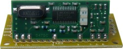
This is an example of the receiver fitted.
Connecting to Microcontroller
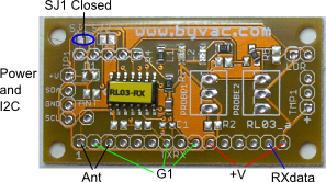
The receiver can be connected to any I2C master, it does not have pull up resistors on board so the master should provide those, which is normally the case. The receiver is an I2C device running at 100kHz and so will interface with all microcontrollers. The address is fixed at 0x40 but can be changed by request if required.
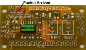
The pad on the left hand side of SJ2 will go high when a new packet has been received and will go low when the I2C reads the bus. It is highly recommended that this pad is connected and used rather than poling the I2C bus. The reason for this is that when the I2C is active the receiver cannot listen for incoming signals.
If polling the I2C must be used then chose a reasonable time say more than 10 seconds between reads.
I2C Command
The address is 0x40 (8bit) and 0x20 (7bit - Arduino, RPi). There are 11 bytes to a packet using the format below. PS is the packet store of which there are 5 slots S1 to S5 plus the packet ID. There are two receiver boards RX can store up to 8 packets (0-7) and the RXA board can store up to 99 packets (PS0-PS98).
| PS0 | ID | S1h | S1l | S2h | S2l | S3h | S3l | S4h | S4l | S5h | S5l |
| PS1 | ID | S1h | S1l | S2h | S2l | S3h | S3l | S4h | S4l | S5h | S5l |
| PS2 | ID | S1h | S1l | S2h | S2l | S3h | S3l | S4h | S4l | S5h | S5l |
| PS3 | ID | S1h | S1l | S2h | S2l | S3h | S3l | S4h | S4l | S5h | S5l |
| PS4 | ID | S1h | S1l | S2h | S2l | S3h | S3l | S4h | S4l | S5h | S5l |
| PS5 | ID | S1h | S1l | S2h | S2l | S3h | S3l | S4h | S4l | S5h | S5l |
| PS6 | ID | S1h | S1l | S2h | S2l | S3h | S3l | S4h | S4l | S5h | S5l |
| PS7 | ID | S1h | S1l | S2h | S2l | S3h | S3l | S4h | S4l | S5h | S5l |
| RXA** | |||||||||||
| 0x80 | * |
RX type receiver board can store system + 7 packets of information from 7 different transmitters
RXA type receiver board can store system + 99 packets of information from 99 different transmitters
The first packet store 0 (PS0) contains system information. To read a packet, send the packet store number followed by 11 reads to get the 11 bytes that make up a packet. For example to read packet store 3 would be:
- send i2c start with address of 0x40 (or write address of 0x20)
- send 3
- send stop
- send i2c start with address of 0x41 (or read address of 0x20)
- read 10 bytes with ACK
- read 1 byte with NACK (last byte)
- send stop
*Reading a special packet slot 0x80 (128) will clear all of the current storage data, the value returned will be 0xaa. The data will also clear if more than 10 bad packets have been consecutively received.
Packet Format
Packets received from the transmitter are stored in the packet store, a new packet with the same ID will overwrite the previous packet and so the only packets in the data store are packets that have different ID's. The receiver keeps track of real time and so the age of the packet which is S5 is updated when read. This gives the age of the packet in seconds.
Packet stores without any information will read as all 0 except for the age which will read the number of seconds since the last reset of the receiver.
The receiver is reset every 23 hours or so and so the maximum age is approximately 82,000 seconds, however the maximum value of a 16 bit number is 65535 and so if the packet reaches that age it will remain at 65535 until another newer packet is received or 1 hour has elapsed. The packet will be removed form the list if it is more than 1 hour old.
The packet consists of the device ID (8 bits) and 5 x 16bit values (S1 to S5) thus making a total of 11 bytes. The actual number of bytes transmitted is more than this because Hamming code correction and CRC checking is used.
The 16 bit values are stored in high-low format so to reconstruct the original 16 bit number:
v = high*256
v = v + low
The system packet that will occupy PS0 contains the following information:
ID always 10
S1: Device ID 16bits normally 9003, this will indicate the device variation, if any
S2: Firmware version 16bits, 212 is version 2.12
S3: Number of bad packets received, i.e. packet received but bad check sum
S4: Last packet ID received (low byte)
S5: Time when latest packet was received. This is updated each time a new packet is received.
The other packet formats are fully described in the sensor options on the transmitter page but here is a summary.
ID: The ID of the transmitter
S1: Always ADC value from LDR
S2 to S3: Sensor information depends on what sensors are connected to the TX
S4: Battery voltage of the transmitter * 100 so 521 would be 5.21V
S5: Age of the packet in seconds, so if this was received 1 minute ago the age would be 60. This is used for ascertaining the validity of the packet.
Tips
The best way to use the device is to have a GPIO input connected to the packet indicator pad (left hand side of SJ2). The GPIO can then be polled or connected to an input to wait for it to go high. Something like the following:
- Wait for packet indicator to go high
- Read the system packet S4, this will give the packet that has just been received
- Read the packet ID given by S4
It would also be wise to reject any packet that was old. The definition of old would of course depend on the system.
If just a temperature reading say is required from a particular ID then there is no need for the GPIO, simply read the I2C when required. But don't forget that when reading the I2C no packet information can be received and so packets can be missed.