BV4244
This is a 'front pack' with a 16 way touch pad (with 32 key buffer) for use with standard 20x4 HD44780 type displays. It also has a PWM back light output so the back light can be dimmed. The user interface is I2C.
- Data sheet (included assembly instructions if required)
- LCD Controller KS108B
- Overlay samples (png & Inkscape )
- Dimensions
- Arduino
- Raspberry Pi
- ByPic
- FAQ & Tips
- EEPROM utility (python for the RPi)
- Purchase <Byvac Shop> <eBay shop>
- User comments, feedback
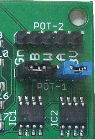
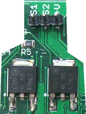
Connector
From top to bottom [2]
| Pin | Description |
| BELL (out) |
Momentarily goes high when a key is touched, this can be attached to a buzzer to get audio feedback |
| KEY (out) |
Goes low only when a key is being touched otherwise it is high |
| INT (out) |
Normally high, will go low if there are any keys in the buffer. |
| RST (in) |
Reset; leave disconnected, pull low to reset the device. |
| +V | 2.5V to 5V [1] |
| SDA | I2C Data |
| GND | Ground |
| SCL | I2C Clock |
[1] The device can handle these voltages but the actual voltage used will be determined by the display that is fitted.
[2] Errata: refers to PCB verisonBV4244-a The silk screen pin designation has been wrongly marked. This table is the correct pin designations from top to bottom
Arduino
- BV4244 Library and samples - version 1.05
The above zip file has a selection of examples and the library itself:
Keypad Section
void clrBuf(); Clears / resets the keypad buffer, the buffer is 79 bytes big
uint8_t keysBuf(); Returns the number of keys in the buffer
uint8_t key(); removes and returns the key in the buffer, if no key, returns a 0
uint8_t keyIn(uint8_t k); See if 'k' is in the buffer, 0 if not or a number representing its position in the buffer
uint8_t scan(); Returns the scan code if a pad is being touched, if no pad being touched then returns 0
void avg(uint16_t *b); Supply a buffer 8 integers big and this will return the 8 averages from each channel
void delta(uint16_t *b); Supply a buffer 8 integers big and this will return the delta value for each channel. The delta value is the difference between an average value and the touched value, if no pad is thouched the delaa value will therefore be 0
void EEreset(); Resets all EEPROM values back to their defaults
void sleep(); Shuts down device to save power, can only be awakened with a reset or I2C activity. NOTE the keypad will not respond when in sleep mode.
void beep(uint8 beepMs); Beeps the beeper for number of mS, max 255
EEPROM Section
NOTE: Values written to the EEPROM will not take effect until the device is reset. For what the values mean consult the data sheet in the Device Parameters section.
void trigger(uint16_t value); Write a new trigger value to the EEPROM
void hyst(uint8_t value); Writes a new hysteresis value to EEPROM
void keyPtr(uint8_t value); Writes a new key pointer value to EEPROM
void keySize(uint8_t value); Writes a new key table size value to EEPROM
void debounce(uint8_t value); Writes a new debounce value to EEPROM
void repeat(uint16_t value); Writes a new repeat key value to EEPROM
void timebase(uint8_t value); Writes a new timebase value to EEPROM
void defaultBL(uint8_t value); Writes a new default back light value to EEPROM
System Section
void EEwrite(uint8_t adr, uint8_t value); Writes a value to the specified EEPROM address
uint8_t EEread(uint8_t adr); Reads an EEPROM value at the specified address
uint16_t ID(); Gets the device id number as an integer, in this case 4242
void Version(uint8_t *b); Gets the firmware version as two bytes
LCD Section
The LCD secion uses exactly** the same function names as used in the LiquidCrystal library and so will not be repeated here. There are however a few extra functions listed
void lcd_reset(); Sends a reset to the LCD display
void bl(uint8_t m v); The back light has a value range of 0 to 10
void lcd_startMsg(); This simply displays the message stored in EEPROM
** the current LiquidCrystal setCursor() starts row and column numbers from 0 whereas the BV4244 setCursor() starts them from 1.
Getting Started
Use the device exactly as any other I2C device, wiring:
| Arduino | BV4244 |
| A5 | SCL |
| Ground | GND |
| A4 | SDA |
| 3.3V or 5V (depends on LCD display) | V+ |
Unzip the library file or use the include Library>>add .zip and try one of the examples.
Tuning
This should not really be necessary but it is there is a utility that will display all of the channel average and delta values. Tuning details are covered in the data sheet.
Raspberry Pi
Connecting
Most LCD displays require 5V and so connect the 5V Rpi supply to the device. This will not effect the I2C data and clock lines that will be still at 3.3V doe to the pull up resistors incorporated into the RPi
| RPi | BV4244 |
| SCL | SCL |
| Ground | GND |
| SDA | SDA |
| 3.3V or 5V (depends on LCD display) | V+ |
You will needs to install the basic RPI I2C. This can now also be partly done via the config tool (sudo raspi-config).
This is a normal I2C device that can easily be used with Python. Connect and use i2cdetect to make sure it is connected okay.
pi@raspberrypi ~ $ i2cdetect -y 1
0 1 2 3 4 5 6 7 8 9 a b c d e f
00: -- -- -- -- -- -- -- -- -- -- -- -- --
10: -- -- -- -- -- -- -- -- -- -- -- -- -- -- -- --
20: -- -- -- -- -- -- -- -- -- -- -- -- -- -- -- --
30: -- -- -- -- -- -- -- -- -- -- -- -- 3c -- -- --
40: -- -- -- -- -- -- -- -- -- -- -- -- -- -- -- --
50: -- -- -- -- -- -- -- -- -- -- -- -- -- -- -- --
60: -- -- -- -- -- -- -- -- -- -- -- -- -- -- -- --
70: -- -- -- -- -- -- -- --
pi@raspberrypi ~ $
The address is 0x3c as shown. Just to get a feel of how it works i2ctools can be used:
- i2cset -y 1 0x3c 31 1 // clears the LCD screen by sending command 1
- i2cset -y 1 0x3c 32 65 // prints 'A' to the display
- i2cget -y 1 0x3c 3 // gets a key from the keypad buffer
On the last command "i2cget -y 1 0x3c 3" if it returns 0, touch a key and send the command again, you will see that the key value will now be fetched.
Python
There is a python class that can be incorporated into Python programs.
wget http://www.byvac.com//downloads/Python/bv4243.py
The program does use notSMB and so that will also be required. As an example the following is a Python interactive session at the command line.
Python 2.7.3 (default, Mar 18 2014, 05:13:23)
[GCC 4.6.3] on linux2
Type "help", "copyright", "credits" or "license" for more information.
>>> import bv4243 as b
>>> ui = b.BV4243(0x3c,1)
>>> ui.clear()
>>> ui.cursor()
>>> ui.lcdPrint("Fred")
>>> ui.bl(10,0,0)
>>>
ByPic
// #include http://www.byvac.com/dwonloads/BV4243/test44.bas
Some random functions
Overlays & DXF
The keypad is designed as a front panel and comes with just a bare PCB, the front of which has the touch pads on. The idea is to create your own design to suit a particular project.
- Overlay - zip file, this included DXF and SVG
The layouts file contains an svg file. This can be opened and edited in inkscape which is free and rather good. The file contains an accurate representation of the layout. This can be used to print an overlay for the device.
Tips: (*** This is for the BV4242 but the techniques still apply ***)
Sticky backed glossy photo paper was used to produce the layouts that were made a bit oversized. When printed the rectangle hole for the LCD display was cut out so as to position the overlay.

This covered the PCB. The excess was cut off from the back.

Another good material is Vinyl but it is a bit thinner and so the PCB shows through. Clear sticky back material could also be used. The LCD rectangle could be left unprinted and stuck over the whole PCB, thus making it weather resistant.
Dimensions

There is also the dimension, dxf drawing in the overlay zip file above. The depth of the device will of course be determined by the LCD display fitted but using a standard display it is about 10mm.
FAQ
- How do I move the cursor to another line on the display?
This is done with a command and applies if type HD44780 or similar controller is fitted to the display (most are or compatible).
A command is used with a value to move the cursor to a particular position on the display, the start of the line has the following command values:
- line 1 128 (0x80)
- line 2 192 (0xc0)
- line 3 148 (0x94)
- line 4 212 (0xd4)
to select a position along the line (column) just add to the value so for example line 2 column 3 would be a value of 192+3 = 195
- I2C Swamp
The device is constantly monitoring the keypad but the I2C has priority over this and will always be acknowledged. If the host is constantly reading or writing to the device then it will have less time to do its job. If it is necessary to respond quickly to a key pad touch then use one of the interrupt pins rather than poling the I2C.
- My display has too few pins and won't fit?
The device is designed to take BOTH the newer RGB back light type displays and the ordinary single back light displays. The RGB displays have 18 pins and the normal displays have 16 pins so to fit a normal display 2 pins need cutting off. This is explained in the data sheet, display fitting section.
- Soldering

Some displays have a very tall glass area, in this case the pins will not go all the way through the holes on the display. For this instance, solder the pins on the underside of the display, it is a little more tricky but works well.
User Comments
-
I found that sometimes after a reboot of the teensy there were
still keys in the key buffer, sometimes unprocessed from or during
the reboot, sometimes spurious.
The BV4244 has a hardware reset key, also 'clear key buffer' command can be send during that start up.
History
- Release August 2016