I2CN12
Introduction
This is an I2C to UART bridge, designed to give an extra UART to a microcontroller when only I2C is available. In addition it has 4 GPIO and 1 DAC
- Extra UART
- 3.3V OR 5V GPIO outputs x 4 *
- 3.3V OR 5V GPIO inputs x 4 *
- Digital to Analogue converter with 32 steps (DAC) x 1
- Analogue to digital converter 10bits with voltage reference x 4 *
* There are 4 pins which share the above functionality so any of the pins can be individually set to the functions above. If supplied from 5V then the pins and UART will be 5V operation. If supplied form 3.3V then they will be 3.3V operation.
Library
There is just one library available written for the ESP8266 MicroPython. or the RPi. Updated December 2018
Data sheet in pdf format.
Device
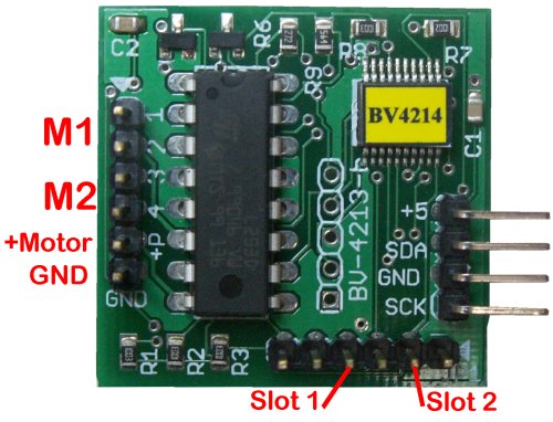
Currently there are two types I2CN12 a generic device for any microcontroller and I2CN12W a Wemos shield type device.
|
|
|
| Generic version | Wemos Shield |
Generic Version I2CN12
This version is a pre-programmed IC. There is a label on top with the pin functions marked
| Pin | Function | Pin | Function |
| 1 | SDA | 14 | Ground |
| 2 | Interrupt | 13 | CT |
| 3 | P2 | 12 | DAC |
| 4 | RS | 11 | P1 |
| 5 | RX | 10 | SCL |
| 6 | TX | 9 | SDA |
| 7 | P4 | 8 | P3 |
Pin Out
For further information on the pinouts and what they do, refer to the data sheet.
Pull Ups
All I2C buses require pull up resistors. There are no pull up resistors on this board for very good reason. They are normally on the microcontroller board (master) but not always (Arduino). Depending on where the pull up resistors are connected to will determine the i2c interface voltage.

This arrangement is used for a 3.3V microcontroller. V+ can be supplied with 3.3V OR 5V should a 5V GPIO and UART be required. There is no need for this on an Rpi as it already has pull ups built in.
Raspberry Pi

Above shows that the RPi can control 5V devices.
Wemos Shield
The image shows the PC version that attached to the Wemos as a shield. It is driven through the I2C interface of pins SCL D1 (GPIO5) and SDA D2 (GPIO4). The Wemos can can also have MicroPython firmware installed.
** At this point in time there are no wemos libraries available, just micropython **
In this instance female connectors have been used so that it can be mounted thus:

Male pins could also be used and mounted wither top or bottom of the Wemos.

Here a HC12 (433MhZ transceiver) is being used on the serial port as the serial port on the Wemos is used for programming. An extra GPIO pin is also uses to program the HC12 if required.
Pull Ups
The I2C bus requires pull up resistors and these have not been fitted to the wemos, they are however optional on the I2CN12. Only one set of pull ups are requires as long as they are somewhere on the I2C bus.


The image shows the solder jumper enabling the pull ups.
MicroPython
The library above will give access to the UART in a very simple way. MicroPython should be installed on the ESP8266 see the MicroPython web site.
Unzip the library and save it to the ESP8266
>>> import i2cn12
>>> d = i2cn12.I2CN12()
>>> d.scan()
Assuming all of the defaults scan should come back with 36. If not do some checking such as are the pull ups in place? Is the device plugged in the right way round.
The library is ready to use.
The default options are as below and can be changed by using the keywords
d=i2c12.I2C12(adr=35,scl=5,sda=4,trig=0x1a)
For example if the SCL and SDA were on say 12 and 14 respecively then the initialisation would be:
>>> d = i2cn12.I2CN12(scl=12,sda=14)
The numbers refer to the GPIO numbers
To see the command that are available open the library and see the name of the functions.
** The above is just an example. Detailed instructions are in the data sheet

