BV108
<pictures>(to follow)
The BV108 is a battery operated wifi sender that periodically sends a message with temperature and optional humidity information to a listening server or an email address via pushingbox.
- Quick setup guide pdf
- ESP8266 Firmware
Developer Information
The BV108 is supplied as a user device, however there are connectors that can make the device much more usefull than just a sender.
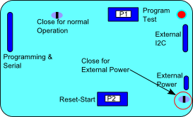
The basic BV108A comes with the top solder jumper closed and the bottom (external power) open. This is to allow for battery operation.
The top solder jumper connects GPIO16 to reset. This is required to wake up the device after it comes out of deep sleep. It does however get in the way of the DTR pin which is useful for development so this would normally be open when used for that purpose.
The bottom solder jumper is connected to the 3.3V regulator, again this consumes a tiny amount of current and so for battery operation, which is connected directly to the ESP8266, the 3.3V regulator is disconnected form the circuit via this pad. When developing, this will normally be closed and a 5V USB supply can be used. Depending on the regulator fitted the input voltage can be from 6V to 16V.
Programming and Serial
| Pin | Description |
| TX | Goes to the UTXD pin of the ESP8266 |
| RX | Goes to the URXD pin of the ESP8266 |
| V+ | Input to the 3.3V regulator, maximum input voltage 6V |
| DTR | Connected to the RTS pin of the ESP8266, can reset the device via the COM terminal. |
| RTS | Goes to GPIO0. This pin can be controlled via the Python programming utility |
| GND |
External I2C
This can be connected to an external I2C device and controlled via the serial commands which are built in to the firmware. The commands are on the 'details' link for the relevant firmware.
Circuit Diagram