BV4115_2
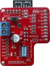
Version 1 with yellow label.
Contents
Wi-Fi Relay Controller with mobile web page
Version 2
There is no hardware difference between version 1 and version 2. The difference is with the firmware installed on the ESP8266 and also on the BV4115 microcontroller. In addition this is only a WiFi option, no serial version is available.
Resources
- Data sheet
- Quick Start First connection to network
- New setup
Description
This is a relay controller, designed to operate up to 8, 5V relays, the controller does not have any relays itself and only outputs a signal for which to operate the relay with. The firmware exposes an HTTP API and so is easily operated form any browser.
Hardware
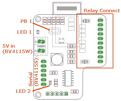
The relay connector is designed for 2,4 and 8 way relays and these can be selected by the various solder jumpers. Details of which are in the data sheet.
LED 1 is the power LED and LED 2 is the wi-fi configuration indicator.
Using
The first thing to do is to set the ESP WiFi module to the home IP address and also let it know how to connect to the network. This is described in the Quick Start guide and also on this site, wifi setup, browser method. Once a connection has been established the device can be accessed through a normal browser.
This exposes an HTTP API and so is designed to be used via the HTTP protocol, i.e. in a browser. The following is a summary of commands are available that return or do something. A full description of the commands are in the data sheet.
- help
- relay/name/action/time
- relay/off
- relay/status
- eeprom/w/address/value [*]
- eeprom/r/address/bytes
- device/id
- device/fw
- device/reset
- device/eereset
- code/bytes
- code/off
[*] Writing, changing eeprom values will not take effect until the device is reset.
A full description of the commands is in the data sheet.Examples:

This example will turn on relay 'a' in 5 seconds from sending the command. Commands can be entered in a browser as shown above. In this case the relay controllers IP address is 192.168.11.39. The command simply follows the address.
All commands return the Ack which in this case the default is 'A'. This is so that an automated program can know when a command has been successful. An unsuccessful command will return 'N' . The actual values 'A' and 'N' are stored in EEPROM and so can be changed.

In this case 5 eeprom values have been requested from address 0 and the result is shown.
JavaScript
JS can be used to write a browser application. A very simple example is given here:

NOTE: This requires ESP firmware F1.9.8 or above
Example 1
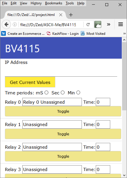
A more complex example is here:

This can be directly accessed form http://www.byvac.com/wifi/relay/relay.htm or the source code can be downloaded from here and run locally.
The above code used EEPROM location 3 to set the number of relays in use, so this should be done first using a browser. For example if 4 relays are attached to the relay on the address in the image:

The above will set the number of relays and show the correct number in the JavaScript above.
Example2
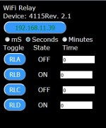
This is a bit simpler example (zip file of source code). This can store the relay name in the html local store so you can associate a relay with a particular function.
To make it work better change the ACK from 'A' (65) to (6) by altering the value in EEPROM location 4,do this in a browser address bar, assuming the address of the controller is 192.168.11.55:
192.168.11.55/eeprom/w/4/6%0d%0a
Update: add the ip address to the url to automatically open and get relay details. for example:
http://www.byvac.com/downloads/BV4115/project.html?192.168.11.55
NOTE: For reliability, use your own server or local 'project.html' files as the above is not always guaranteed to be there.
Security
To make the device a bit more secure a keyword can be set up which must be placed in front of the command. By default this is switched off and so no keyword is needed. This is done in the browser as the examples above.
code/1234 (sets a keyword 1234)
From now on this will be needed for all commands so the above eeprom read would need to be :
1234/eeprom/r/0/5
This is of course not completely secure as the HTTP GET request is in plane text so can be read by anybody with a suitable interest. It does however provide some level of protection.
A Socket
The device 'transparently' uses the HTTP GET protocol, that is to say if a request is made through a browser then it can handle the request and send back to the browser the correct response. This does not preclude it from being accessed via a normal socket using just TCP. For example the commands can still be sent via telnet, putty or other socket type program.
Access to the Wi-Fi link
The device consists of two microcontrollers, one handling the wifi and the other handling the relays. The relay microcontroller commands have been described above. There is also another set of commands that refer directly to the wifi controller. All of these commands begin with +++. These commands can also be entered via a browser address for example.

The +++ip command has been entered that returns the current ip address, this command can also be used to set the ip address to something different.
An important command is +++rr this will perform a hardware reset on the relay controller. This may sometimes be needed at first switch on.
The wifi controller firmware version is vF1_1.9.7 A full set of the wifi controller commands at that link.
Troubleshooting
1) Use the Quick Start guide to set the initial conditions for the ESP8266 wifi module. This will be done through the browser interface.
Lets assume that your wifi router is 192.168.5.1, and you have set the BV4115 to station mode (1) 192.168.5.30 on port 80
2) Open a command window and type ping 192.168.5.30. This is the first test, if everything is okay then you will get a reply, if not then press the button for longer than 6 seconds and follow the Quick Start instructions again. Some item to check:
- Make sure that the SSID and password match your home router exactly
- Make sure that the ESP8266 is in station mode
- Check the IP address and port number
- POWER SUPPLY: The ESP8266 requires a good power supply, some wallwart type 5V supplies will simply not work. This is usually indicated by the LED staying illuminated at a low level (dim).
- Check that the system flag is 16 (0x10), if set to 0 then there will be no browser access.
- Push the button for > 6 seconds and reconfigure using 192.168.4.1 in the browser address
3) If and only if ping works, try http://192.168.5.1/+++info (in the browser address bar) to get more information about how the ESP is configured. Using the +++ commands talk directly to the WiFi and not the relays.
4) If you have got +++info working the relay commands should work i.e. http://192.168.5.30/help
5) If there is no reply to http://192.168.5.30/help then try http://192.168.5.30/+++restto=300
6) now see if http://192.168.5.30/help works, if not then do a factory reset as follows:
There is a row of 5 holes at the bottom of the PCB, the square hole is marked 1
o o o o x
5 4 3 2 1
a) remover the power
b) short out (connect together) holes 3 and 4, tweezers are good for this
c) apply power
d) remove power
e) remove short
http://192.168.5.30/help should now work, if not then please contact me.
7) One last thing to do. When the relay responds to a command it may be set up with an 'A' to acknowledge it has received this command. When used with a browser the WiFi firmware does not recognise 'A' and so will take a long time to respond. If it is too long, it may result in a time out. To address this tow things need to be done:
(This is not necessary for devices purchased after 7 Sept 2016, Version 2.3 as the default has been set to ACK 6)
- http://192.168.5.30/eeprom/w/4/6%0d%0a
- http://192.168.5.30/+++rr (or power off / on )
History
May 2016 Release version 2
20 May 2016 New ESP firmware F1_9.8 which has an access control * response so can be used on a dissimilar network.