BV510
Contents
- Set up
- Set up 2
- Power Supply
- Relays
- Digital Potentiometers
- MOSFET
- Motor
- 1-Wire
- GPIO
- End Stop Sensor
- I2C Master
- List of Commands
- How to Use & WiFi
- Programming re-install firmware
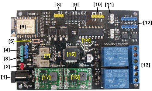
[1] AC or DC power supply input max 28 Volts
[2] DC input max 28 Volts
[3] I2C interface fo master or slave
[4] Serial interface
[5] Wifi - reset button for browser configuration
[6] wifi module acts as a serial bridge for communications
[7] 1-wire temperature probe interface x 2
[8] High current MOSFET switch outputs with variable PWM control
[9] GPIO can be used for digital ADC and other functions, fully programmable
[10] Medium current output to drive 2 DC motors froward and reverse, PWM output for speed control
[11] End stop interface x 2
[12] Digital potentiometers 5k with 64 steps x 2
[13] 10A 250V relays x 2
[14] Wifi UARTt select
[15] 32bit microcontroller running ByPic
[16] 3.3V switching power supply
[16] 5V switching power supply
Introduction
This is a general purpose wifi enabled board. It can read and write information via wifi for example over telnet or it can be used directly via a serial interface. The wifi can contact external sources if required and also given the correct network environment can be controlled externally.
The board is intended to be used in a system that will issue serial commands to it. However it can also run stand alone and be re-programmed over the wifi if required.
Set Up (Method 1 with USB to Serial)
Set up is carried out by the supplied USB to serial device as the wifi is not yet set up although it is possible to set up the device without using the serial connector. Fro that see Set Up 2 below.
Make the following hardware connections with the cable provided:
USB to Serial BV510
GND GND
+5V +V
DTR DT
RXD TX (NOTE swapped)
TXD RX
You may use any terminal program but it may be easier to use bvserial on this page. Set up the Baud rate for 115200 with no hardware handshake or parity, 1 stop bit.
At this point the LED next to the CFG button will be flashing.
NOTE when entering commands cAsE is important and so are "" if required
When using the terminal you should see something line BV510 Ready: and an ok prompt. At the prompt type:
wf_setStation("myssid","mypass")
This will show some errors as the wifi resets, that is normal. Look at the LED and if you have connected to your wifi network it will have gone out. If the wifi cannot connect with your network then the LED will be illuminated steady (not flashing). If that is the case then the SSID and password you have supplied is wrong, so recheck and send again.
Your router will now give the board an IP address. To find out what it is type:
print wifi$("info")
Somewhere at the end of the list will be the IP address, you can also interrogate your router for the list of clients. This is however very inconvenient as the router may change the IP address from time to time. To create a fixed IP address use:
wf_setIp("my address,"router address",port)
Example wf_setIp("192.168.2.180","192.168.2.1",31500)
The first three numbers will be your network, in this case 180 is not being used by anything else. Note that the IP addresses are enclosed in "" but port is not. Agin this will reset the wifi that will show errors this is normal.
** If you get ERROR (0) after immediately typing something then you have typed it wrong, check the spelling and case.
Set up (Method 2 without USB to Serial)
This is a method of setting up the device without the use of the USB to serial connector. It requires that two solder jumpers are unsoldered and also a station device (laptop, pc or tablet) to connect with it.
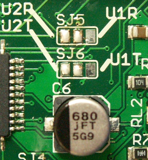
1) SJ5 and SJ6 are normally soldered, remove the solder as shown.
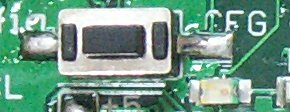
2) Push the CFG button and hold it down until the LED illuminates continuously.
3) The wifi is now in access point mode and the LED will be flashing. Use a station device (laptop, tablet, phone, pec etc.) and connect with the wifi device, there is no password needed.
4) When connected use the browser to address 192.168.4.1 and yo will get a yellow web page (configuration index), select the station setup link and fill in the boxes with the information for your network.
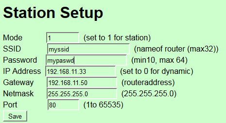
This is an example you MUST set MODE to 1 to connect with your existing network. Press save and then Save Changes in the configuration index. After a few moments you will be able to telnet to the device using the IP and port given.
Power Supply
The power supply consists of a bridge rectifier a 5V switching regulator and a 3.3V switching regulator. The power supplied can therefore be from 6V to 28V AC or DC
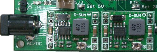
AC is via the 2.1mm power connector and DC is via the two pins marked DC. SJ3 and SJ4 are open at manufacture to allow the supply voltages to be set. Do not adjust the potentiometers otherwise damage to the board WILL occur.
Relays
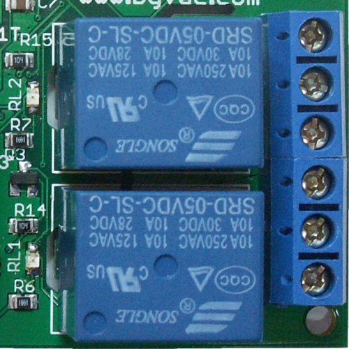
The relays are driven from the 5V supply via MOSFET transistors and both have an indicator LED. Tey are single pole double throw switches and so can either be normally on or normally off depending on which terminals are used.
Relay Firmware
rla(time,action)
rlb(time,action)
The relays can be set to go off (action=0) or come on (action=1) at a given time. The time is in mS and can be up to a maximum value of 4,294,967,295 (49 days)
The rating of the relays is marked on the top and cab vary but t is normally 10A.
DAC or Digital Potentiometers
There are two 64 step 5K digital potentiometers.


The wiper runs form A to B. If just a DAC is required than 2 jumpers can be used as shown in the picture, this will produce an output varying from 0 to 2.2V
Pot Firmware
- pota(value)
- potb(value)
Value is a number from 0 to 63.
MOSFET
Two MOSFET transistors rated at 60V, 20A
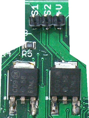
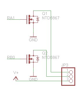
These are N types and so form a switch to ground. They are driven form the microcontroller by a PWM input and so for controlling motors and the like. Diode protection should be used if inductive loads are used.
MOSFET Firmware
- feta(value)
- fetb(value)
Value can range from 0 to 700 with 0 being fully off and 700 being fully on.
Motor
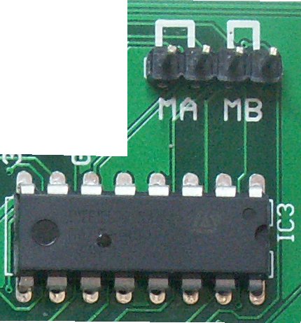
The Motor section uses an L298 which is capable of driving 2 DC motors up to 1.2A (with a heat sink). The firmware is arranged to drive the enable pins via PWM and so each motor can go forward or reverse with a given amount of power.
Motor Firmware
mota(direction,power)
motb(driection,power)
The value of direction is normally 1 or 2 but 0 and 3 will effectively stop the motor. The power value can range from 0 (no power) to 700 (full power).
No protection diodes are needed as they are built into the L239 IC. Although the L293 is designed to power motors it can also be used as a general purpose power output similar to the MOSFET but with reverse capability. The firmware could be refined to implement this for 1 stepper motor but that has not been implemented yet.
1-Wire
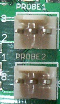 The two connectors marked probe1 and probe2 are designed for two DS18B20 temperature sensors and the firmware will convert the output from these into a temperature reading to 2 decimal places but multiplied by 100. So for example the temperature 21.50 degrees will be 2150. This is better then floating point when used for comparisons.
The firmware is set up for the DS18B20 temperature probes but can be used for other 1-wire devices if required, just minor tweaking will be needed as the drivers are already in place.
1-Wire Firmware
Connection
---------
Q + -
Orientation as shown in the picture, DS18 output is the left hand pin and + is in the middle.
tpa() // gets value of probe a
tbb() // gets value of probe b
The actual probe value a or b is dependent on the ROM id of the probe and so cannot be fixed in firmware or hardware. If 2 probes are connected then they will always relate to each other as either A or B no matter wich plug they are connected to.
GPIO
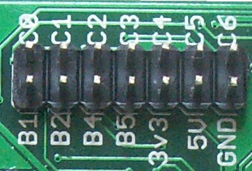 The 2x7 connector can be used as any general purpose I/O. However to make things easier the firmware has been written to use the pins for a specific use.
This can easily be changed by the user at a later date if say all output pins are required.
GPIO Firmware
In the current firmware this gives 5 ADC inputs, 5 outputs and 2 inputs. The firmware names reflect the markings on the PCB
- anb1() // adc on RB1
- anb2() // adc on RB2
- inb4() // digital input
- inb5() // digital input
- anc0() // adc on RC0
- anc1()
- anc2()
- ouc3(n) // digital output on RC3
- ouc4(n)
- ouc5(n)
- ouc6(n)
End Stop
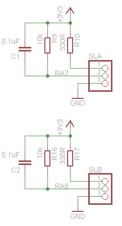 There are 2 circuits that can be wired to infra red end stop or proximity detectors. On the PCB they are marked SLA and SLB
Pin 1 should go to the emitting diode positive and pin 2 should go to the detector positive, these are often marked D+ and E+ respectively. Note that some end stop devices that are mounted on a PCB already have this circuit built in
| Pin1 | E+ to anode of emitting diode (V) |
| Pin2 | D+ Input (output from slot switch) (S) |
| Pin3 | Ground (G) |
For the ready built types with a PCB, resistors R10 and R17 my need to be reduced to 0R (i.e. shorted out as the PCB normally has them in)
I2C
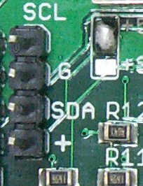 There is a master I2C interface that can use either 5V or 3v3 which is set by the solder jumper next to the interface pins. On this image it is set to 5V. To set to 3V remove the solder from one side of the jumper and apply to the other.
I2C Firmware
This is set to the standard 100kHz clock frequency and has just 2 firmware commands.
i2cf()
i2c(address,out$,in)
The first command i2cf() will return a list of addresses separated by comma of all of the devices on the bus.
The second command allows full interaction with any I2C device and works as follows. The address is the I2C (8 bit) address of the slave device. Out$ is a string of decimal digits separated by a space that you wish to send to the i2c device and in is the number of bytes that are expected back.
To give an example using the DS1307 real time clock. Getting a byte from a register requires a write to set the register and then a read to get the contents of that register, so the read the hours register (2) this would be:
i2c(208,"2",1)
To set the current hour to 3
i2c(208,"2 3",0)
In this case two vales are sent to the i2c and nothing is returned.
List of Commands
Some of the commands are 'internal' and may require a print in front of the command
wifi
- wifi$(cmd$[80]) // sends a command directly to the wifi module see. Returns a string (use print)
- wifiCheck() // returns 1 if wifi is okay
- wf_setStation(ssid$,pass$) // sets wifi to station with the requested SSID and password
- wf_setIp(ip$[20],gate$[20],port$[20]) // sets IP address of station
Other as described above
- help // list commands available
- rla(time,action)
- rlb(time,action)
- pota(value)
- potb(value) // 0 is B end, 63 is A end
- feta(value)
- fetb(value) //0 is off, 700 is full on
- mota(direction, power)
- motb(direction, power)
- tpa()
- tpb()a
- nb1() adc on RB1
- anb2() adc on RB2
- inb4() digital input on RB4
- inb5() digital input on RB5
- anc0() adc on RC0
- anc1()
- anc2()
- ouc3(n) digital output on RC3
- ouc4(n)
- ouc5(n)
- ouc6(n)
- i2cf() finds devices on bus
- i2c(address,out$,in) see instructions
How to Use
For both the RPi and Arduino all that is required is a serial interface.
WiFi

Jumpers SJ6 and SJ6 control the connectivity of the wifi to the board. With both jumpers unsoldered the wifi is disconnected (serially) from the board. This is required if using the USB to serial interface as it interferes with the communication.
To us the wifi as a serial interface then the left hand side jumper need connecting, marked U2R and U2T. This will connect the wifi serial interface with the board. The wifi can now be used instead of the USB to serial.
There are many ways to communicate once the wifi has been set up:
- Telnet
- BVSerial
- Through a browser address bar [1]
- Through javascript. [1]
[1] There are some good examples of using wifi on the bv4115 page.
Full Circuit
Programming (re-installing the firmware)
It has been mentioned that the device can be programmed as a stand alone device and that is correct. It uses ByPc which is a fast scripting language; a cross between basic and C specifically designed for use with a microcontroller.
The best way to get started is to use the quick start guide. The BV510 can be programmed through the wifi connection or through the serial connection. A big advantage of the wifi connection is that you do not need to be physically near the board.
Following the quick start guide further information is here.
The firmware scrip file is below. Typing flclear(0) and then loading the following file
http://www.byvac.com/downloads/BV510/bv510.bas
The head of the file contains all of the includes that can be opened with F8, using the ByPic IDE and so any modifications can be made.


